With the release of the latest version of the CAD4U drawing software it is time to look at what’s been happening to your favourite CAD software.
C-Technik Software, the CAD4U developer, has stated that:
“The main target of the development work for V.22 was making the DXF/DWG drawing data exchange better and supporting 64-Bit operating environment.”
So the first thing to note is that the download now has both 32 and 64 bit versions.
If you have a 64 bit Windows operating system, then we would recommend the 64 bit version as being faster, especially when using graphical functions such as dynamic panning and images. Otherwise you must install the 32 bit version.
As previously indicated, there has been a complete revamp of drawing translation for both import and export of drawings. Most notable is the inclusion of DWG import and export … something that the author thought we would never see! Also, the process has been improved with the introduction of a dialogue window for all settings and mappings for the translation … making the process easier to set-up and more robust:
The new import/export functionality includes:
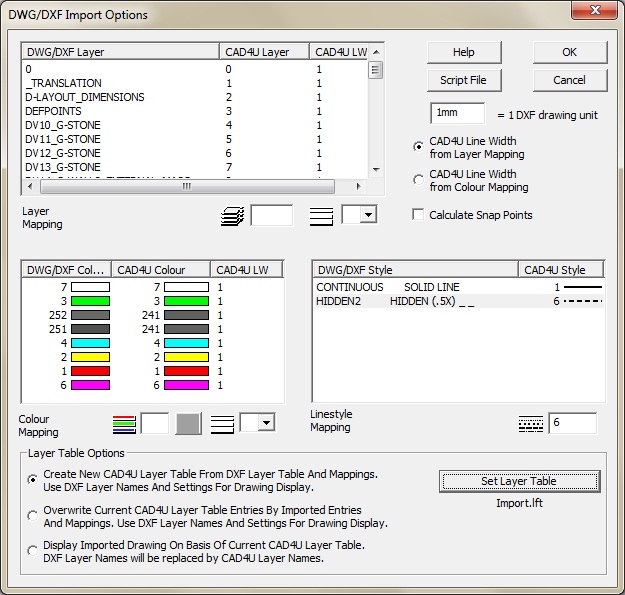
- Colour mapping which now attempts to match the CAD4U colour to the DXF colour automatically.
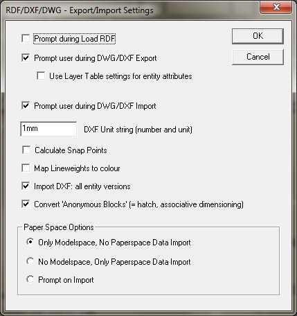
- Colour mapping which allows lineweights to be mapped to colour and the user can choose whether to use this mapping during a DXF Import. This is particularly useful as AutoCAD has never supported lineweights and the AutoCAD user assigns colours to identify different lineweights when printing.
- There is a new option to control the calculation of snap points after importing. If switched OFF, this feature can save a lot of calculation time when larger drawings are imported.
- ‘Extruded entities’ are now fully converted including Arcs, Circles, Inserts, Lines, Polylines and Solids. This improves DXF and DWG imports and avoids mirrored display of extruded entities.
- In the DWG/DXF Import Options dialogue, the user is given a prompt if the CAD4U colours are close in RGB to the PAPER colour. This gives the user a chance to change the colours to something more appropriate, before continuing the import.
- During IMPORT an ‘anonymous block’ flag is used to mark these entities (i.e. DXF hatch and associative dimensioning records) to allow the new VIEW FILTER (see below) to be used to control the display and selection of these blocks. Additionally, users can also choose to ignore ‘anonymous blocks’ when importing DWG/DXF, in which case these records are simply ignored during the translation.
- A CAD4U library page is no longer presented at the completion of the import.
- LIBRARY / DWG EXPORT A new function which exports the current drawing to .DWG file.
- There are now three options for how the Layer Table is updated during DWG/DXF Import:1. Create a new table, use automatic colour mapping and use layer names from DXF layer table.2. Overwrite the names of the present layer table with the incoming DXF/DWG layer names.3. Keep the present CAD4U layer table entries meaning that the DXF colours and layer names will be lost.
- There are also new options for the Paperspace handling:1. Only Modelspace, no Paperspace Data translated.2. No Modelspace, only Paperspace Data translated.3. The user is prompted when importing the drawing.

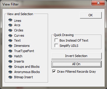
The VIEW FILTER is a new function intended to replace the old Speed Filter (that nobody ever seemed to use!?). The View Filter will filter records for group edit selection as well as display and individual entities including lines, arcs, circles and polylines can be chosen for filtering (See View Filter dialogue below) All functions requiring selection use the VIEW FILTER settings. INSERTS and BLOCKS display overrides all other records. If INSERTS or BLOCKS display is on, all sub-records of the INSERTS or BLOCKS are displayed regardless of the other record filter options. This makes it easier to edit only inserts or blocks. ‘Draw Filtered Records Gray’ will show selected records in grey, except for Bitmap Inserts, which are skipped.
The new CHECK LIBRARY function can correct library problems including:
- Zero length inserts and blocks which are replaced with a placeholder.
- Missing inserts and blocks which are replaced with a placeholder.
- An integrity check can be run on inserts and blocks, and if mistakes are found they are corrected. If there are corrections required, the corrected inserts and blocks can be written back to disk. Checks carried out include ‘impossible radii’ and ‘out of range’ (infinite) coordinates and are similar to the checks earlier CAD4U versions made when filing or exporting.
- Purge blocks is similar to the previous Purge Blocks but quicker and deletes more blocks than previously. The user can select any combination of these and stop the operations with the provided “stop” button and at no risk to the library data.
Other odds & sods include:
- PUBLISH, PUBLISH ZOOMVIEW and PUBLISH SELECTION are intended to be used when the user wants to output to formats such as PDF and XPS. Drawings are rendered to a bitmap on the host PC (rather than by the printer) and then sent to the chosen printer output. This is especially helpful when images with transparency are used in a drawing. We would not recommend this method for pure vector output as the resolution will suffer … use the standard print functionality.
 LOAD RDF and SAVE RDF have been added to the LIBRARY toolbar for quicker access to RDF files. Also note that the prompt for ‘Reassign Layers’, when loading an RDF, can be turned off in SETTINGS/RDF/DXF/DWG Options. See top check box in options dialogue on the right ‘Prompt during Load RDF’. This makes the use of RDF’s for filing more streamlined than ever before by removing the last connection to the file’s ‘archiving’ past history. Also note that the loaded file’s name is displayed in the window header and is used for print output making PDF creation quicker, easier and less error prone.
- The VIEW Toolbar has been extended with the VIEW FILTER and COLOUR FILTER functions.
- The layer table can now be set to a different file from the original wc_layer.lft. If the user saves or loads a table in the SETTINGS / LAYER TABLE dialogue or when importing DWG/DXF, then the layer table name will become the one the user has selected (e.g. Import.lft as shown above in the DWG/DXF Import Options dialogue). The new filename is saved in the settings file so it will be used for the next session. If there is no settings file or the user does not load or save to a new name, then wc_layer.lft will be used. The file name of the layer table is now displayed at the bottom of the LAYER PALETTE.
- The whole library box is highlighted and a small dot is drawn in the background colour to indicate the box position.
